-
Interactive DashboardsCreate interactive BI dashboards with dynamic visuals.
-
End-User BI ReportsCreate and deploy enterprise BI reports for use in any vertical.
-
Wyn AlertsSet up always-on threshold notifications and alerts.
-
Localization SupportChange titles, labels, text explanations, and more.
-
Wyn ArchitectureA lightweight server offers flexible deployment.
-
 Wyn Enterprise 7.1 is ReleasedThis release emphasizes Wyn document embedding and enhanced analytical express...
 -
 Choosing an Embedded BI Solution for SaaS ProvidersAdding BI features to your applications will improve your products, better serve your customers, and more. But where to start? In this guide, we discuss the many options.
-
Visual GalleryInteractive sample dashboards and reports.
-
BlogExplore Wyn, BI trends, and more.
-
WebinarsDiscover live and on-demand webinars.
-
Customer SuccessVisualize operational efficiency and streamline manufacturing processes.
-
Knowledge BaseGet quick answers with articles and guides.
-
VideosVideo tutorials, trends and best practices.
-
WhitepapersDetailed reports on the latest trends in BI.
-
 Choosing an Embedded BI Solution for SaaS ProvidersAdding BI features to your applications will impr...
 -
- Getting Started
- Administration Guide
-
User Guide
- An Introduction to Wyn Enterprise
- Document Portal for End Users
- Data Governance and Modeling
- View and Manage Documents
- Working with Resources
- Working with Reports
- Working with Dashboards
- Working with Notebooks
- Wyn Analytical Expressions
- Section 508 Compliance
- Subscribe to RSS Feed for Wyn Builds Site
- Developer Guide
Create 3D Scene
3D Scene is a visualization tool in Wyn Enterprise designed to represent three-dimensional data using 3D models and their associated data. Comprising three integral sections — 3D models, lights, and data layers — further elaborated in subsequent sections of this document, the 3D Scene in Wyn Enterprise facilitates the addition of data labels to models sourced from data repositories, enhancing the informational depth of your scene.
Utilizing Babylon.js for the construction, loading, and display of the 3D Scene, Wyn Enterprise supports the integration of dynamic data scripts tailored to your specific requirements within the 3D environment. These scenes can be seamlessly embedded into your dashboards, offering an enhanced visualization of your data. See the 3D Scene help article for detailed information on embedding 3D Scenes within your dashboard.
3D Scene Designer
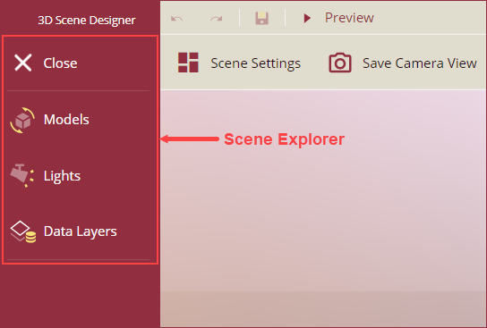
The image below displays the elements of the 3D Scene Designer page, followed by a detailed explanation of these elements.
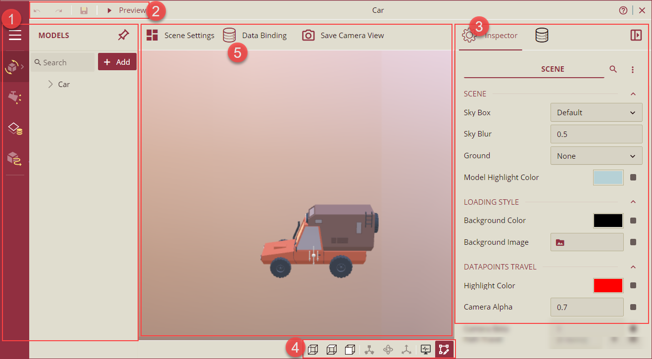
Scene Explorer: Displays the hierarchical tree of all the elements of the 3D Scene listed below. You can hide, delete, or focus each scene element from the Scene Explorer.
Models: Lists all the 3D models of the scene in a hierarchical model tree structure. 3D models are divided into two parts as described below.
Transform Node: Acts as a container to group multiple meshes together. The Transform Node allows collective transformations such as moving, rotating, or scaling.
Mesh: Individual objects of 3D models that make up the scene. Each mesh can be transformed individually,
Lights: Includes options to add or remove lights. By default, light with intensity 1 is added to the 3D scene upon initialization. The available light options are explained below,
Directional Light: Directional lights are used as a distant source of light that hits all the objects in a 3D Scene from the same angle, regardless of the object's position.
Point Light: Point Light sources are the light sources used to produce a uniform beam of light with the illumination scattered in all directions. Point Light sources are also known as omnidirectional lights.
Spot Light: Spot Light sources are generally used for artificial light sources such as flashlights, headlights, and searchlights. The moving spotlight will illuminate a small area of the scene only.
Hemispheric Light: Hemispheric Light sources are used to stimulate ambient environment light.
Data Layer: Data Layers display the data related to the model objects of the 3D Scene. You can also bind data to the data layers, which include the following data roles,
Value: Represents the sum or count value associated with the data fields.
Mesh Name: Represents the name of the 3D object within the application.
Tooltip: Provides additional information on a data point, usually on mouse hover.
See the Manage Data Layers article for more information.
Animations: Provides unified animation management for different types of animations in a 3D scene. There are three types of animations available in Wyn Enterprise,
Built-in Animation: Built-in animations are the animations that were created during the model-making process. These animations are embedded in the scene itself. These built-in animations can be controlled (start, stop, or pause) here. See the Manage Animations section for more information.
Node Animation: Node animations are custom animations created for models of the 3D scene. The node animations are defined within the scene settings and include the following actions: change color, hide, move, move (offset), rotation, and scale. See the Manage Animations section for more information.
Data Layer Animation: Data layer animations are custom animations created for data layers of the scene. These animations are also defined within the scene settings and include the following actions: change color, hide, move (offset), and scale. See the Manage Animations section for more information.
Command Bar: Provides quick access to essential functions like Undo, Redo, Save, Preview, and Exit.
Settings: Includes the Inspector Panel to manage the properties of scene objects and the Data Binding Panel to bind data to the scene.
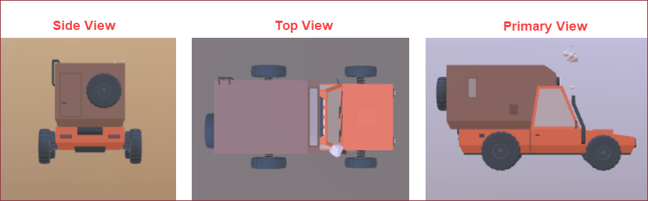
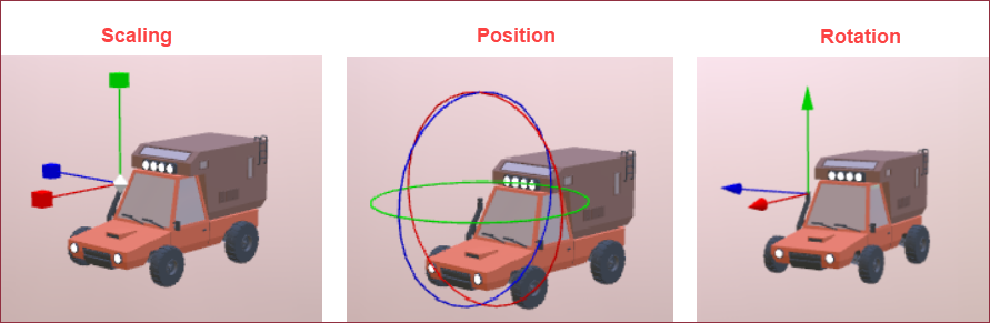
Status Bar: Included options to change the view directions (Side View, Top View, and Primary View), mesh selection modes (Scaling, Position, and Rotation), and highlighting.
Canvas: The main area to render and interact with the 3D scene. It provides a visual representation of the scene and lets you engage with the 3D objects. The following two options are available in the Canvas area,
Scene Settings: Allows you to configure an entire scene. Click to access and modify specific settings in the Inspector Panel.
Save Camera View: Save the current camera perspective using this button. The most recently saved perspective will be used on the preview.
This article provides information on creating 3D Scenes in Wyn Enterprise.
Prepare 3D Model
When creating a 3D Scene, 3D models are required to display the entire scene and the associated data. Upload a model file. GLB format using the Upload feature on the Resource Portal. See the Upload article for more information on uploading files in Wyn Enterprise.
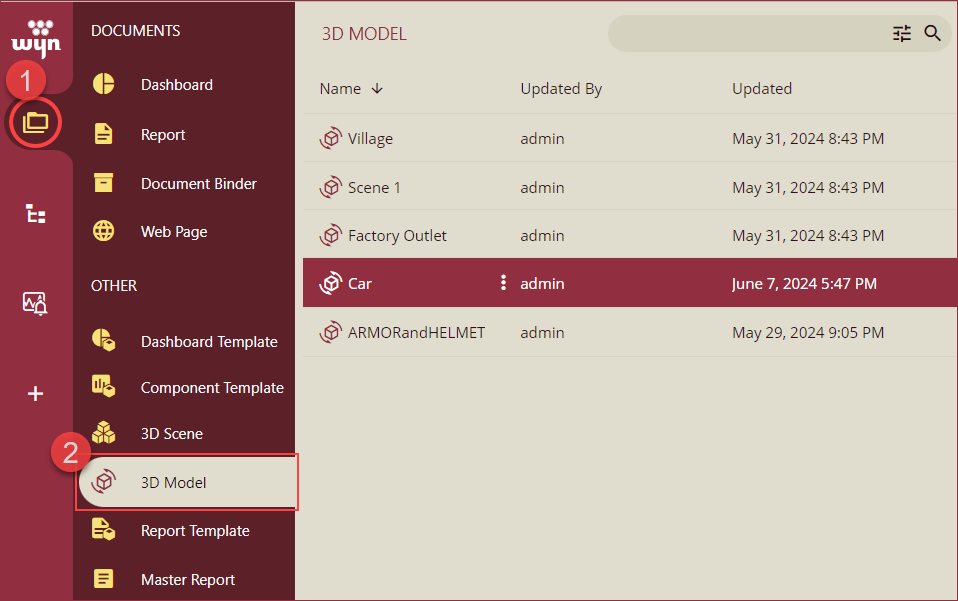
Uploaded 3D Models are listed on the 3D Models document list on the Resource Portal under the Document Types section.
Create 3D Scene
To create a 3D Scene from the Resource Portal. Follow these steps,
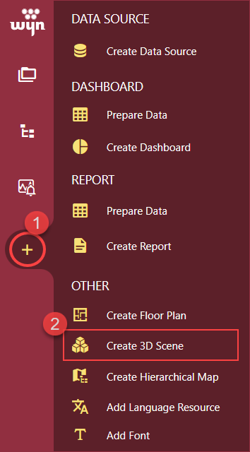
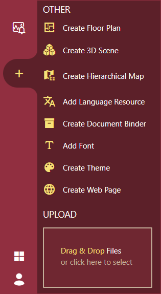
Click the + (create) button.
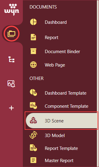
Click Create 3D Scene to open the 3D Scene Designer.
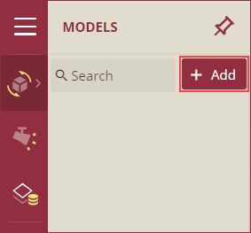
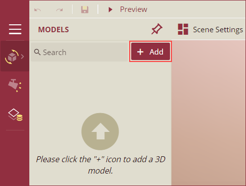
To add a 3D Model to the scene, click the + Add button in the Models section of the Scene Explorer. This will open the Model Manager.

Select a 3D model prepared earlier from the Shared tab of the Model Manager. Use the search bar to search for a model from the list. Click Ok to add the model to the 3D Scene.
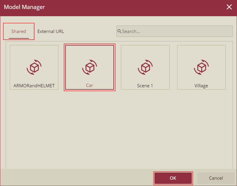
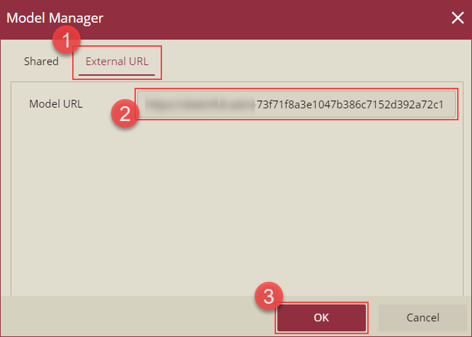
To use a 3D model available on an external URL, navigate to the External URL tab and enter the URL in the Model URL input box. Click Ok to add the model to the 3D Scene.
You can now use the Scene Explorer to add or manage Models, Lights, and Data Layers.
Use the Inspector Panel on the right side to manage the Scene Settings.
Use the Status bar to perform the following:
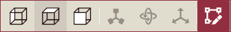
Change View Direction: Select an option to change the view direction to side, top, or primary view. All three views of the 3D model of a car are shown in the image below.
Modify Mesh: Select an option to adjust the scale, position, and rotation of the selected mesh. The image below shows all three modification options applied to a 3D model of a car.
Highlight: Click the highlight button to highlight the selected node on the canvas area. To remove the highlight, click the highlight button again.
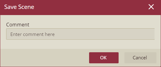
Click the save button on the command bar, enter a name for the scene, select a Category (optional), and add a comment (optional) in the Save Scene popup. Click Ok to finish.
Scene Explorer
Add or manage the Models, Lights, and Data Layers of the 3D Scenes from the Scene Explorer. Click the scene menu button to expand the scene explorer and select one of the following:
Manage Models
Add 3D models to the scene using the + Add button.
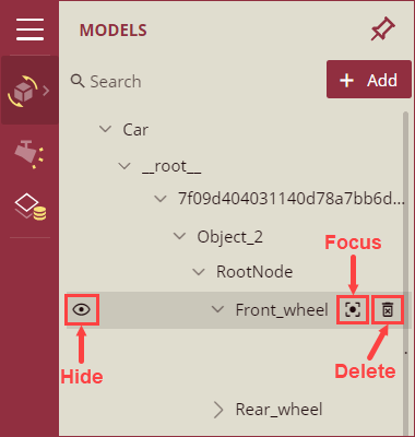
To hide, focus, or delete a transform node or mesh, hover over it and click the corresponding buttons.
Select a transform node or mesh and manage the following properties using the Inspector Panel:
General
Property | Description |
|---|---|
Name | To change the name of the node or mesh, enter the name in the input box. |
Transformation
Property | Description |
|---|---|
Position | To change the horizontal position, vertical position, or depth of the node or mesh, enter the corresponding X, Y, and Z coordinate values in the input box with a space between each value, or click the expand button and enter the corresponding coordinates. |
Rotation | To change the orientation of the selected node or mesh, enter the X, Y, and Z axis coordinates to rotate it around the local X, Y, and Z axes. |
Scaling | To adjust the size of the node or mesh along the local X, Y, and Z axes, enter the X, Y, and Z coordinate values in the input box with a space between each value, or click the expand button and enter the corresponding coordinates. |
Auto Loop Camera Settings
Property | Description |
|---|---|
Preview Camera | Click this button to adjust the camera view to the specified Alpha, Beta, and Distance values. |
Apply Editor Camera | Click this button to set the Alpha, Beta, and Distance values as the current camera view. Clicking the Preview Camera button will now display this camera view. |
Alpha | Enter an angle (in radians) to change the horizontal angle of the camera around the node or mesh. |
Beta | Enter an angle (in radians) to change the vertical angle of the camera around the node or mesh. |
Distance | Enter a distance (in centimeters) to change the distance of the camera from the selected node or mesh. |
Manage Lights
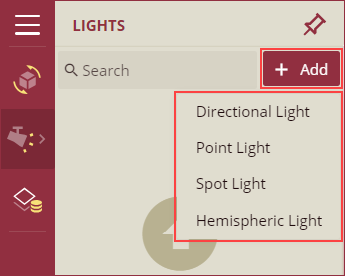
To add light to the scene, click the + Add button and select one from the following: Directional Light, Point Light, Spot Light, or Hemispheric Light.
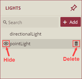
To hide or delete a light, hover over it and click the corresponding option.
Select a light and manage the following settings using the Inspector Panel.
Property
Description
Name
Displays the name of the selected light.
Light Type
Displays the type of the selected light.
Intensity
Displays the intensity of the light falling on the 3D object. The default value is 1.
Position
Displays the position of the light source with X, Y, and Z coordinates, each separated by a space. This option is available for Point and Spot lights only.
Direction
Displays the vector direction of the light with X, Y, and Z coordinates, each separated by a space. This option is available for Directional, Spot, and Hemispheric lights only.
Manage Data Layers
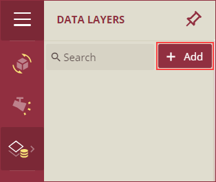
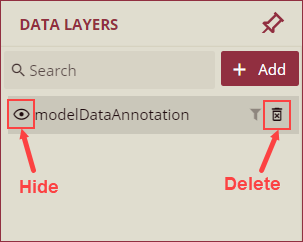
To add a data layer to the scene, click the + Add button. A data layer (modelDataAnnotation) will be added to the list.
To disable or delete the data layer, hover over it and click the corresponding option. You can also add filters to the data layers using the filter icon on hover. See the Filter Data Attributes help article for more information.
See the Manage Data Layers help article for information on binding data to layers and managing the data layer settings, including conditional formatting.
Manage Animations
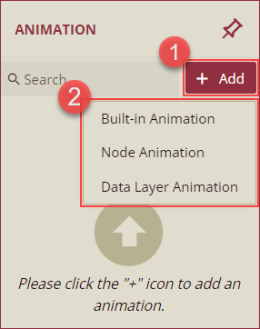
To add an animation to the scene, click + Add and select one from the following options: Built-in Animation, Node animation, or Data Layer Animation.
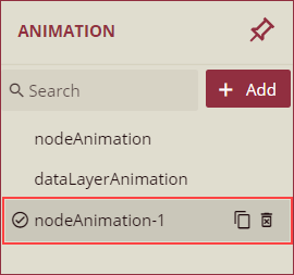
To enable/disable, hide, or delete an animation, hover and click the corresponding animation.
Select an animation and use the Inspector Panel to manage the following settings.
Common Properties
Property
Description
Animation Name
Specify the name of the animation.
Animation Type
Select the type of animation to apply to the 3D model object from the dropdown. The available options are,
Change Color: To animate the color change of 3D objects, select Change Color and select a color using the Color property.
Hide: To animate the visibility of 3D objects, select Hide.
Move: To animate the position of 3D objects, select Move.
Move(Offset): To define the positional change of 3D objects of the scene during the animation, select Move (Offset).
Rotation: To animate the rotation of 3D objects, select Rotation.
Scale: To animate the scale of 3D objects in the scene, select Scale.
Loop Mode
Select a loop mode for the animation from the dropdown. The available options are,
Once: The animation plays only once and then stops.
Repeat: The animation repeats continuously, starting over each time it completes its cycle.
Delay (second)
Set the delay time before the animation starts, measured in seconds.
Duration (seconds)
Set the duration of the animation, measured in seconds.
Trigger Type
Select the trigger type that initiates the animation. The available options are -
Scene Loaded: The animation starts automatically when the scene is fully loaded.
Condition: The animation is triggered when a specific condition set in the Trigger Condition property is met.
Trigger Condition
This property is only visible when the Condition option is selected in the Trigger Type property dropdown. Click on the input box and specify the Condition Settings to trigger the animation.
Click the input box of the Target Field to access the Data Binding Settings and select a dataset and the target value. See the Conditional Format article for more information. You can also create filters using the Filter tab. See the Filter Data article for more information on filtering data in Wyn.
Built-in Animation
Property
Description
Built-in Animation
Select a built-in animation from the dropdown.
Node Animation
Property
Description
Node Name
Enter the name of the target mesh or node.
Data Layer Animation
Property
Description
Data Layer
Select a data layer from the dropdown.
Animation Validation
If there is a problem with any of the animations, then an error will be displayed in the animation list.
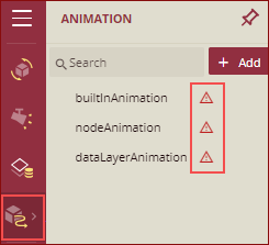
You can hover over the error to see the error details.
Listed below in the table are the conditions under which the error message will be displayed.
Animation | Condition for Error Message |
|---|---|
Built-in Animation | 1. Built-in Animation is not selected from the dropdown list 2. The selected built-in animation is deleted from the scene. |
Node Animation | 1. There is no Node Name 2. Node is deleted from the scene or renamed. |
DataLayer Animation | 1. Not bound with the DataLayer. 2. Bound DataLayer is deleted from the scene. |
Example-1
Data Layer Animation: If the data layer on which the animation is applied is deleted, then an error message will be displayed, as shown below.
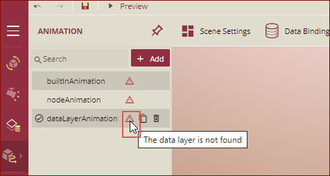
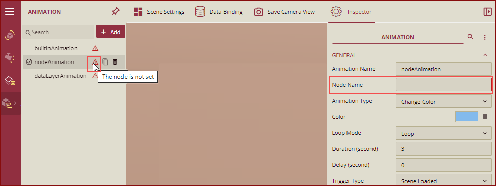
Example-2
Node Animation: If the Node Name is not specified while adding the animation, then an error message will be displayed as shown below.
Data Binding Setting on Node Animation and DataLayer Animation
For some animation types (Move, Rotation, Move (offset), Scale), there are two types of data binding settings: Constant Value and Data Layer Value. The Node and DataLayer Animation support both of these data binding settings.
The source settings for Data Layer Value are different for different animation types:
Node Animation: You can freely select the data model and fields.
Data Layer Animation: You can only select data fields that are bound to the data layer.
Example: Databinding setting on Node Animation
Set up a node (house 3) to move through real-time data.
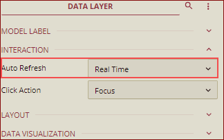
Create a data layer and set up the associated dataset.

Set the dataset to be automatically refreshed to a scheduled or real-time refresh. In this example, we have set it to Real Time.
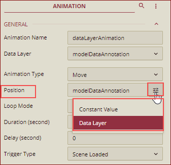
Add a Node Animation. In this example, we have added the Animation Type as Move.
From the Position option, select the Data Binding.
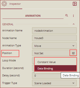
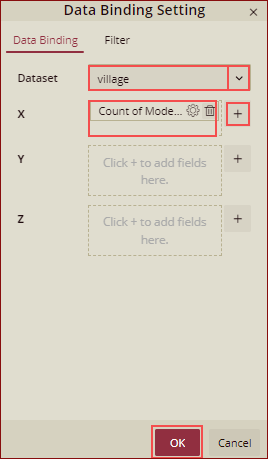
Data Binding Setting dialog box is displayed.
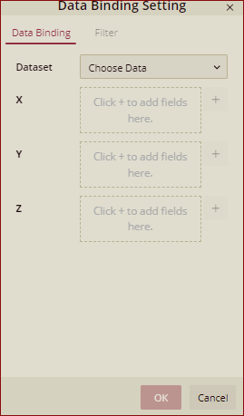
Select the data from the Dataset drop-down list. If there is no data binding set in the x/y/z direction, the current value of the node is used in that direction.
For example, we have selected only the x field, and y and z are not set.
So, on preview, the house only moves in the x direction as shown below.
Example: Databinding setting on DataLayer Animation
Set up a node (house 3) to move through real-time data.
Create a data layer and set up the associated dataset.
Add a DataLayer Animation. In this example, we have added the Animation Type as Move.
From the Position option, select the Data Layer.
Data Binding Setting dialog box is displayed.
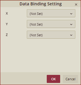
Select the data from the Dataset drop-down list. If there is no data binding set in the x/y/z direction, the current value of the node is used in that direction.
For example, we have selected data only for the x field, and y and z are not set.
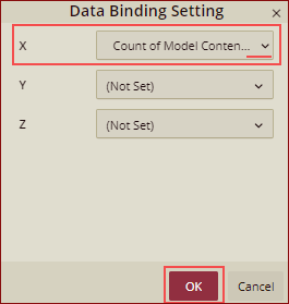
So, on preview, the house only moves in the x direction as shown below.
View and Manage 3D Scenes
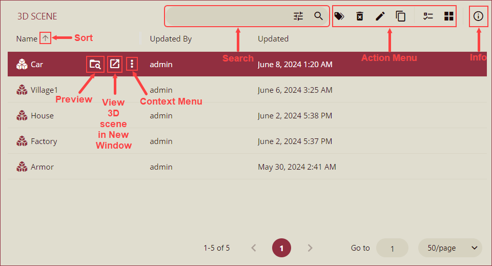
Navigate to Document Types >> 3D Scene.
A list of all the available 3D scenes will appear on your screen.
Use sorting on column headers, the preview button to render the scene in the same window, and the View 3D Scene in New Window button to open the scene in a new window.
Use the context menu to perform the following: Edit 3D Scene, Duplicate, Copy URL, Categorize, Rename, Delete, and Download.
Use the search bar and action menu on the top right corner to search, edit category, delete, edit, duplicate, show checkbox, and enable tile view. Use the Info icon to view the document information and history.
Example Scenario
In this example, we will create a 3D Scene of a Village with model houses, lights, and data layers from the Resource Portal.
Prepare a 3D model using the Upload feature and click the Create 3D Scene option to open the 3D Scene Designer.
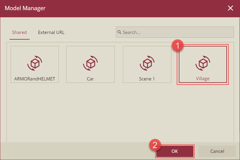
Click the + Add button under the Models section to open the Model Manager.
Select the Village model and click Ok to apply.
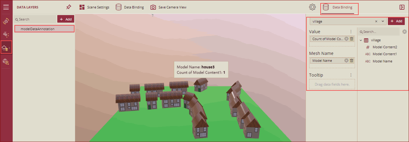
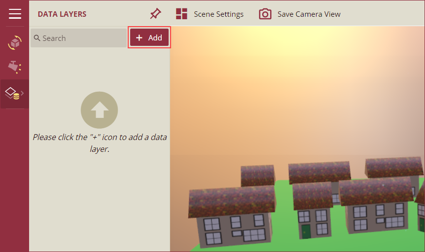
A village scene will be added to the Canvas area. From Scene Explorer, navigate to the Data Layers section and use the + Add button to add a data layer to the scene.
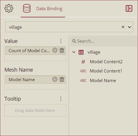
Select the Village dataset to bind data to the scene. Drag and drop the Model Content 1 data fields onto the Value data role and the Model Name data field on the Mesh Name data role.
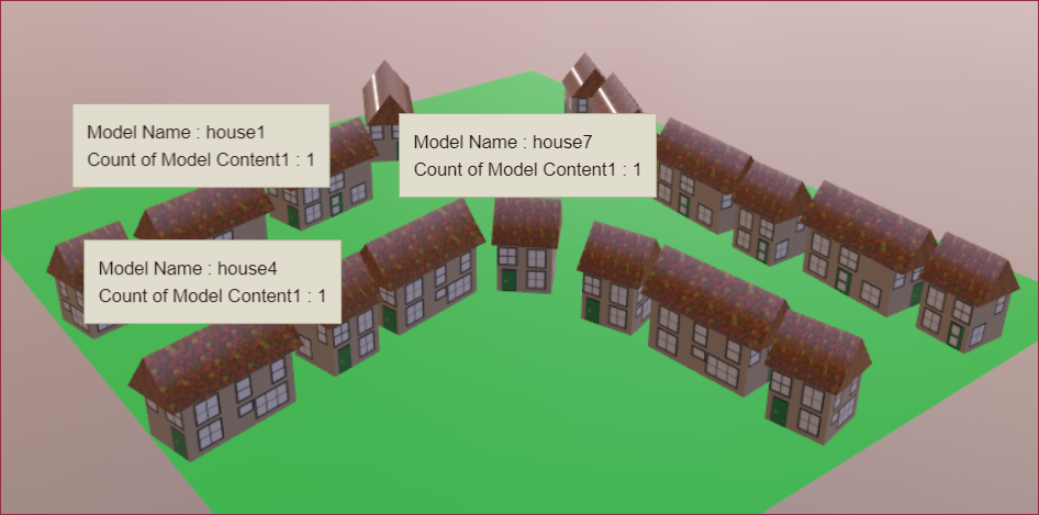
Click the Preview button to render the scene. Notice the data labels above houses 1, 4, and 7; these appear by binding the Village dataset fields to the scene.
Click Save and enter a name for the scene. Click Ok to finish.
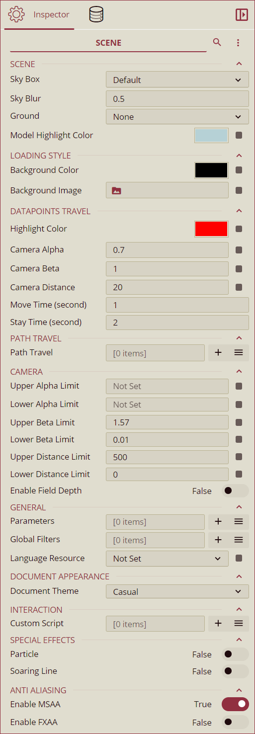
Scene Settings
SCENE
Property | Description |
|---|---|
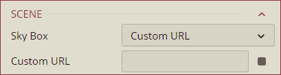
Sky Box | To change the sky background of a 3D Scene, select an option from the dropdown. The available options are Default, Studio, Sky, Lilienstien, CapeHill, Wastelands Cloud Pure Sky, Custom URL, and None. By default, the Default option is selected.
|
Sky Blur | To control the blurriness of the sky background, add a value greater than 0 in the input box. 0.5 is the default value. |
Ground | Select an option from None or Grid Ground from the dropdown to set the ground background of the scene. By default, the None option is selected. - Grid Ground: Use the Grid Ground option to select a geometrical shape (Geometry1, Geometry 2, etc.) to display the grids in the ground. The Grid Ground dropdown appears on selecting the Grid Ground option from the Ground dropdown. - Background Color: Select a background color for the ground. - Line Color: Select the color of the grid line using this option. |
Model Highlight Color | Set a color to display for the highlighted model object. |
LOADING STYLE
Option | Description |
|---|---|
Background Color | Set the background color that will be displayed while the 3D scene is loading. |
Background Image | Set a custom background image that will appear while the 3D scene is loading. |
DATAPOINTS TRAVEL
Note: With the Wyn Enterprise Release Version v8.0, the Auto Loop settings have been renamed to Data Points Travel.
Option | Description |
|---|---|
Highlight Color | Select the highlight color for the node or mesh using this property. |
Camera Alpha | Set the angle ratio of the alpha camera using this property. |
Camera Beta | Set the angle ratio of the beta camera using this property. The value of the Camera Beta property can range from 0.01 to 1.57 (2/π). |
Camera Distance | Set the distance of the camera from the node or mesh using this property. |
Move Time (seconds) | Set the move time of the camera (in seconds) using this property. |
Stay Time (seconds) | Set the stay time of the camera using this property. |
PATH TRAVEL
Option | Description |
|---|---|
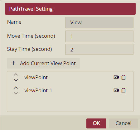
Path Travel | Configure the path that the camera will follow in the 3D scene. To add a new path, click the + Add button, which opens the PathTravel Setting. The following fields are available in the PathTravel Setting:
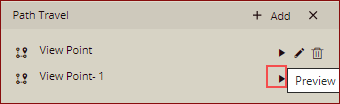
Once the travel path is added, you can click the Preview button to preview the added path details.
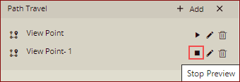
You can also stop the preview by clicking the Stop Preview button. |
CAMERA
Option | Description |
|---|---|
Upper Alpha Limit | Set the upper alpha limit of the camera using this property. |
Lower Alpha Limit | Set the lower alpha limit of the camera using this property. |
Upper Beta Limit | Set the upper beta limit of the camera using this property. The default value is 1.57. |
Lower Beta Limit | Set the lower beta limit of the camera using this property. The default value is 0.01. |
Upper Distance Limit | Set the upper distance limit of the camera using this property. The default value is 500. |
Lower Distance Limit | Set the lower distance limit of the camera using this property. The default value is 0. |
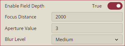
Enable Field Depth | To enable the camera depth of the field effect, set the Enable Field Depth property to True. By default, the value is set to False. On enabling the field depth, the following options appear in the panel, Focus Distance: Set the focus distance of the camera using the Focus Distance option. Aperture Value: Set the aperture coefficient value of the camera using the Aperture Value option. Blur Level: Set the ambiguity level of the camera using the Blur Level dropdown. The available options are Low, Medium, and High.
|
GENERAL
Option | Description |
|---|---|
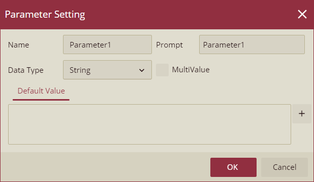
Parameters |
|
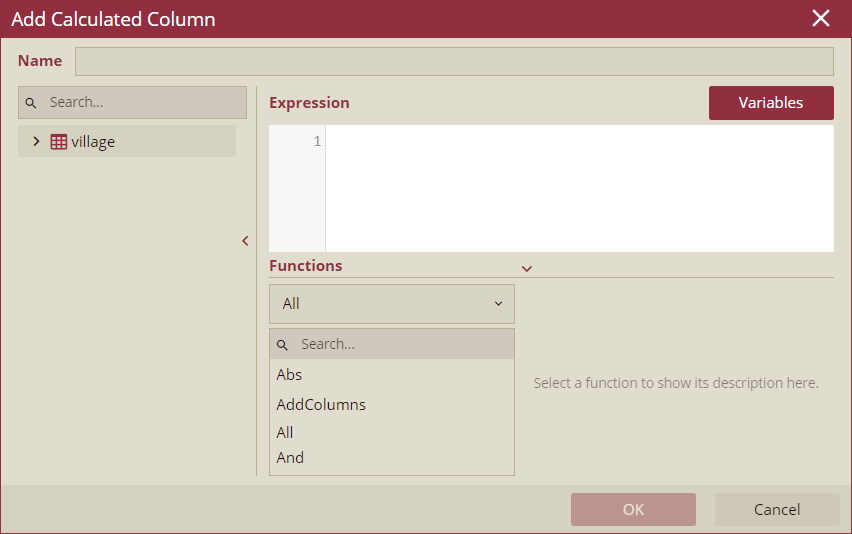
Global Filters | Add global filters to the scene using this property. |
Language Resource | To set a language resource, select a resource from the dropdown. See the Language Resource help doc for more information. |
DOCUMENT APPEARANCE
Option | Description |
|---|---|
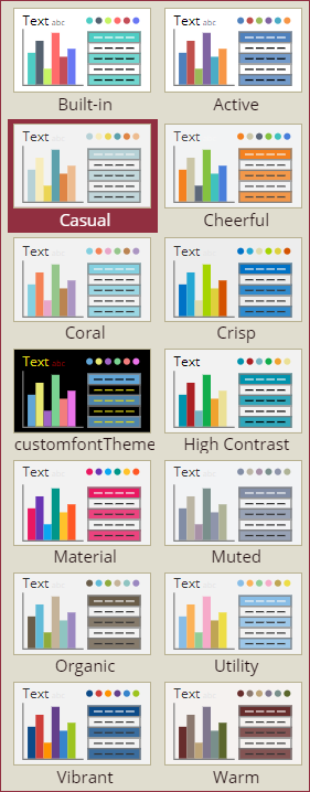
Document Theme | To change the theme of the 3D scene, select a theme from the Document Theme dropdown. The font color, font size, background, etc., will be affected when changing the document theme.
|
INTERACTION
Option | Description |
|---|---|
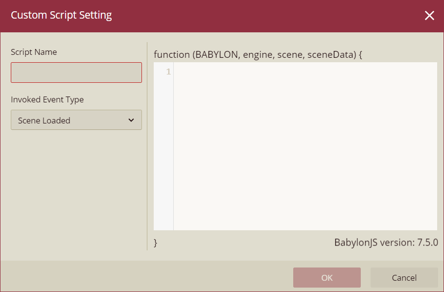
Custom Script | To embed a user code in the 3D scene, click the + button and add the code in the Custom Script Setting pop-up. Wyn Enterprise uses Babylon.js to create dynamic scripts for a 3D scene. See the Customize Using JavaScript help doc for more information on dynamic scripts.
|
SPECIAL EFFECTS
Option | Description |
|---|---|
Particle | To enable particle effect in the 3D scene, set this option to True. By default, the value is set to False. |
Soaring Line | To enable the soaring line effect in the 3D scene, set this option to True. By default, the value is set to False. |
ANTI-ALIASING
Option | Description |
|---|---|